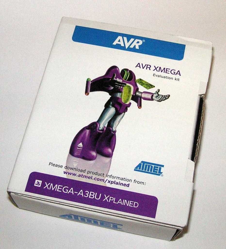
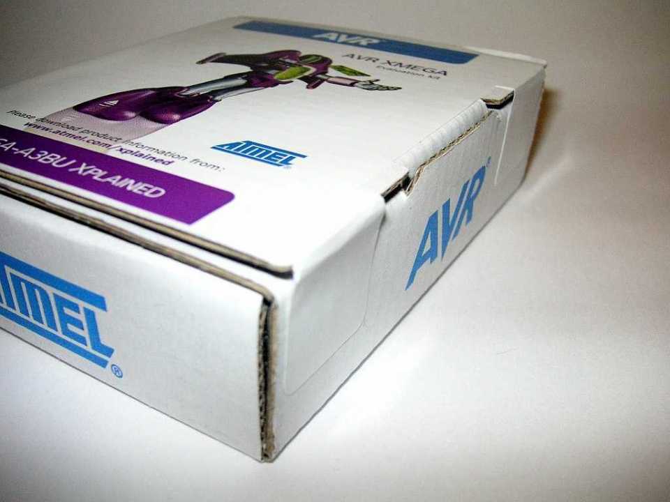
So we cleaned out a storage area and lo and behold, there was an XMEGA Xplained demo board. So I scrounged up a USB cable and plugged it into my computer. I don’t have Studio 6 installed yet, but I thought it would be fun to just un-box it. This is what happened:
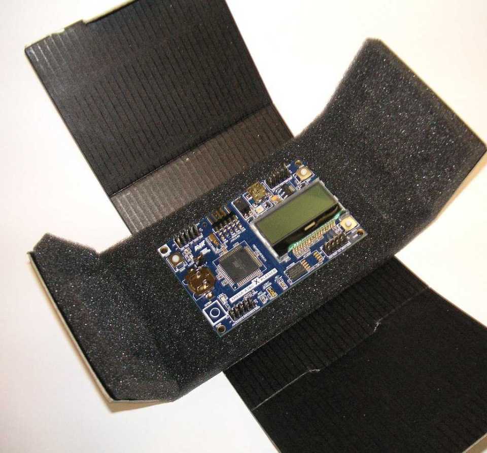
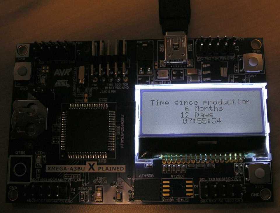
This is what is inside. There is that great LCD, a CR1225 battery for the real-time-clock (RTC), 3 tact switches and a touch switch, a temp sensor, a light sensor, all the signals on headers, and a JTAG port so you can hang a Dragon on it and see inside the chip while it executes. Sweet.
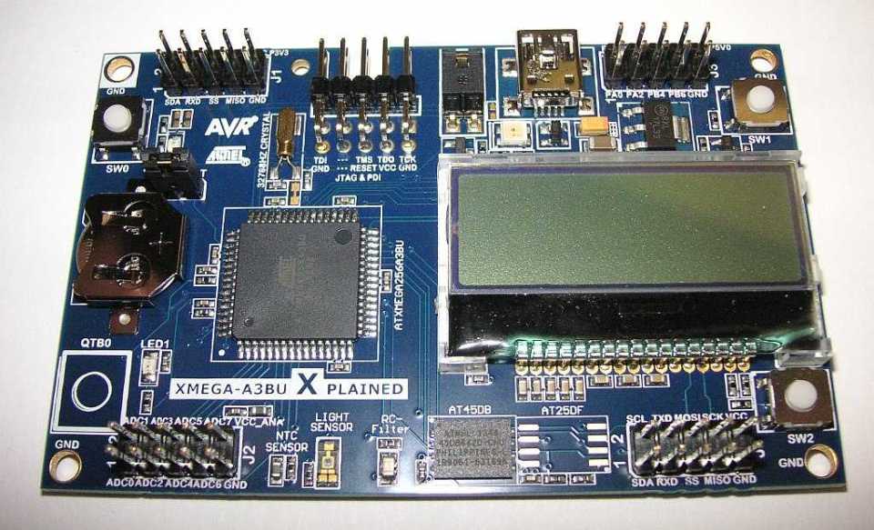
Here is a close-up. Oh, there is a non-volatile serial memory chip too. Needless to say, I have not read any manuals or paperwork yet, heck I am a man, like my buddy Tim who didn’t read the manual on his $60,000 Cadillac before he drove it to San Diego.

On the backside, you can see the 2010 date, but it turned out the board was way newer, stay tuned. You can see the flux residue where they hand-soldered the LCD. You can’t send an LCD through an IR reflow oven.
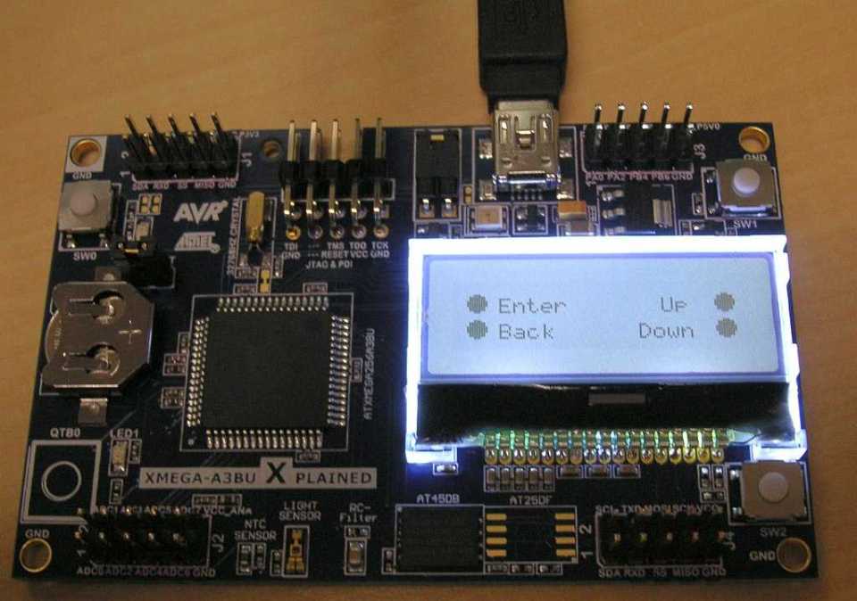
I stick a USB cable on it, and wow, it has a backlight on the LCD. It was obvious that the welcome screen here is telling you how to navigate the pre-installed program. That is not a touch-screen, it is telling you the tact switches and the one touch pad on bottom left are your navigation buttons.
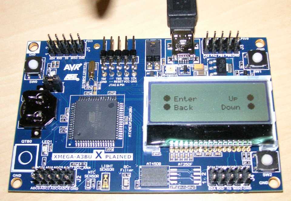
Here is the screen with a flash picture—you can read the LCD either way. You can bet I am thinking how to mount this on my Harley and make a voltmeter/ammeter, temp sensor system out of it.
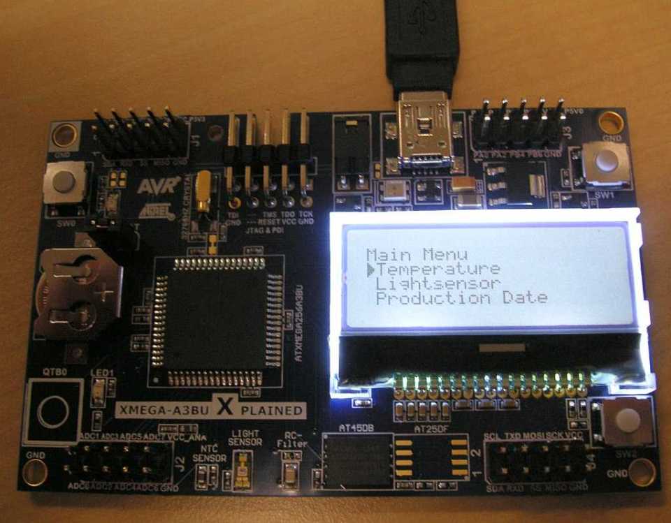
This is what you see if you press “Enter” (the top left button). It’s a sub-menu that displays the temperature, the light intensity, or the production date.
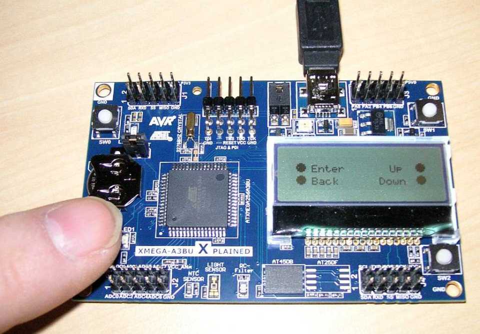
It took me a while to figure out that there was a touch-pad on the bottom left instead of a tact switch. This is how you go back up the menu tree.
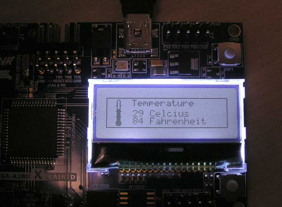
Here is the temperature display. It seems pretty accurate, despite the board saying “NTC SENSOR”. I assume there is a linearization program, negative temperature coefficient sensors are notoriously non linear. This is reading hot since I put my finger on the sensor to see it work.

The top menu had more items and would scroll. This is the page for setting date and time. It was set to Norway time, but the date was right after 6 months.
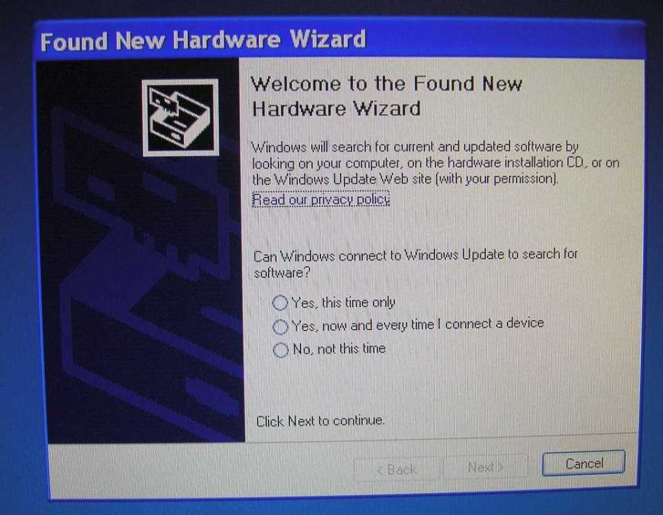
When you stick in the USB the computer prompts you to add a driver. I don’t think that is a good idea. The way this is meant to be used is that you install Studio 6 or use some other IDE or the Atmel Software Framework (ASF) and that has the driver the card needs. So I cancelled. We have all been burned installing things on Windows.
Well this got me pretty fired up. It never occurred to me one of our demo boards would have such a nice program on it pre-loaded. I guess it’s time to install Studio 6. I have been avoiding it, since I am an assembly language dinosaur, and I am sure all this code is in C. After all that is one of the coolest things about AVRs, they were designed to run C and run it well.
In addition to installing our free Studio 6, I will hang a Dragon debugger/emulator onto the card. Thata is another cheap purchase from Atmel, about 50 bucks. There were a couple of those in the storage room too. With a Dragon I can see inside the chip as it runs, single step programs, and read the registers and memory locations.
ECO 1 (engineering change order). Let’s make that navigation screen show more representative symbols for the tact switches, and the touch pad. And let’s move the symbols to the outside corner of the screen, like they are on the PCB (printed circuit board).
ECO 2. Lets add a menu pick to read analog voltages—hang on—holy cow, this thing not only has two 12-bit ADCs, it has 4 comparators. I can see there is a lot to love. And get this—6, count ‘em, 6 USARTs. That will satisfy my buddy Dave who insists on one dedicated UART just for software debug. Sure you can use the debugger when it is hooked to Studio 6 or your IDE, but it is also nice to have a port you can query or that spits out status when the system is deployed in production.
Stay tuned, I will be hooking up one of those Dragons and installing Studio 6 next. Just remember the first rule, never keep a handgun in the same desk you have a computer on. I do expect to be frustrated, it’s been 12 years since I programmed in assembly, and never have used C, but let’s take this little adventure together and see what happens.


Thanks for giving everyone a look at the out of box experience. We have some great kits that you can do many things with. This XMegaA3BU kit is one of my favorites!
LikeLike